
This semester in Physics class, we decided to build a sensor run piano. The project was very challenging, but because of this we were able to learn much more than we thought we would. It has been a lot of fun, and we encourage other students in the future with a lot of ambition to attempt this project due to the very rewarding end results. 🙂
Below, you will find a diagram of the circuit system we used in developing the piano.

The diagram illustrates how the sound was transferred from the Mega, through the resistors, and into the breadboard which essentially connected all the sensors to the Mega. We found that in order for the sensors to function properly, the connection between them must be broken during the start up.
We used 7 sensors during this project to create a full scale octave, with the first sensor doubling as both the first and last note.
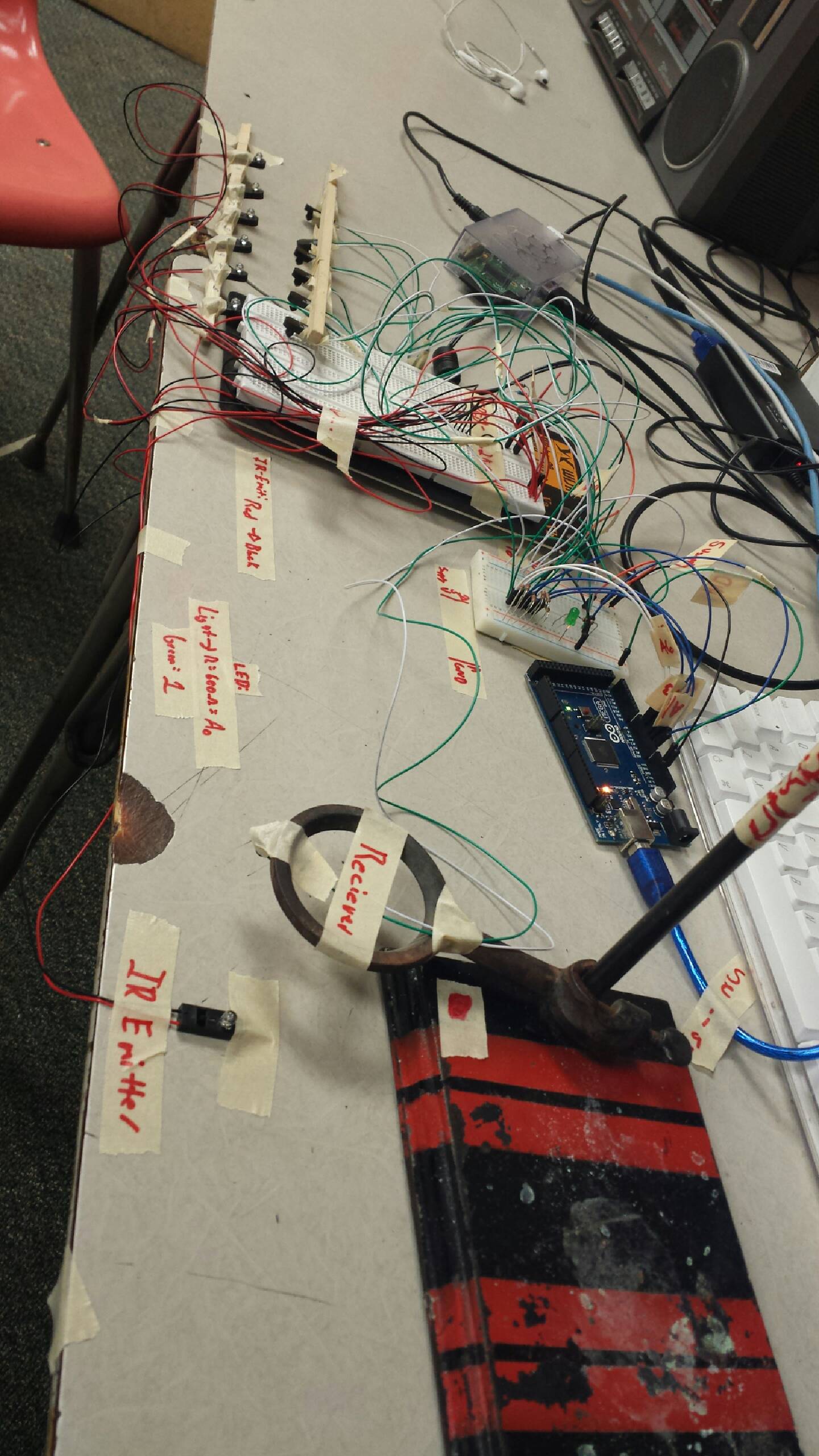

In the photos, the resistors are clearly visible. The resistors were used to reduce current flow, and, at the same time, lower voltage levels within the circuit. Each pair of sensors had separate wires which were inserted into their corresponding places in the breadboard.
Our project originally started with the idea of making a piano staircase in our school. We came down from that cloud pretty quickly when we discovered that the connection between the sensors was only strong enough to stretch a couple inches. Based on this, we decided to stick with a regular piano.

This is a picture of our finished project. Below you will find a link to a video we made showing the piano in ACTION.
It’s pretty exciting, so prepare yourself. 😉
Anyways, we really had fun working on this project and hope that you have gained some knowledge by reading our blog!
